
St. Charles Station Casino is located on Missouri River near Saint Louis, Missouri at approximately 5 miles upstream from its confluence with the Mississippi River (Figure 1). Riverboats and barges forming the casino structures (flotilla) are located in the wake region of a temporary cofferdam structure, immediately downstream from the Missouri State Highway 70 Bridge. This 400 ft wide by 800 ft long cofferdam contains extensive resort facilities that are being constructed (Figure 2). Due to excessive sediment accumulation behind the cofferdam, according to governing laws, the SCSC faces closure if the flotilla looses its floating casino status.
Figure 3 shows the main gambling boat and the cofferdam structure. In order to avoid the high sediment inflow into the flotilla region, a structural solution is proposed to build an 800 ft long sheet-piling diversion wall to enclose the flotilla. It is hoped that this wall would deflect the oncoming sediments away from the casino area and avoid sediment built-up.
The effectiveness and the feasibility of the proposed diversion wall and the identification of stagnation flow regions to improve efficiency of the design were determined by using a state-of-the-art finite element surface flow model (FEM) developed by Hydrau-Tech (Molinas and Hafez, 2000). Low velocity and reverse flow regions exist immediately upstream and downstream from the cofferdam, causing sediment deposition; the FEM turbulence model predicted the location and extent of these zones accurately. Next, utilizing the configuration with the proposed sediment diversion wall, a series of simulation runs were performed to assess the flow in the vicinity of gambling boat. The proposed sediment diversion wall could stop the sediment in contact with the riverbed from entering the casino area; however, the suspended sediment could still enter the flotilla area and settle. Since suspended load forms the majority of oncoming sediment, the flotilla region needed additional protection. Based on the numerical study, a series of structural design modifications were recommended to SCSC. These recommendations aimed at mobilizing the flows behind the cofferdam by diverting flows into the wake region.
Figures 7 and 8 show computed velocities in the vicinity of cofferdam with the proposed sediment diversion wall. In these figures, higher velocities are associated with red tones and lower velocities with blue tones. Figure 7 shows the presence of a recirculation zone behind the cofferdam that extends 4-5 times the length that correspond to observed values.
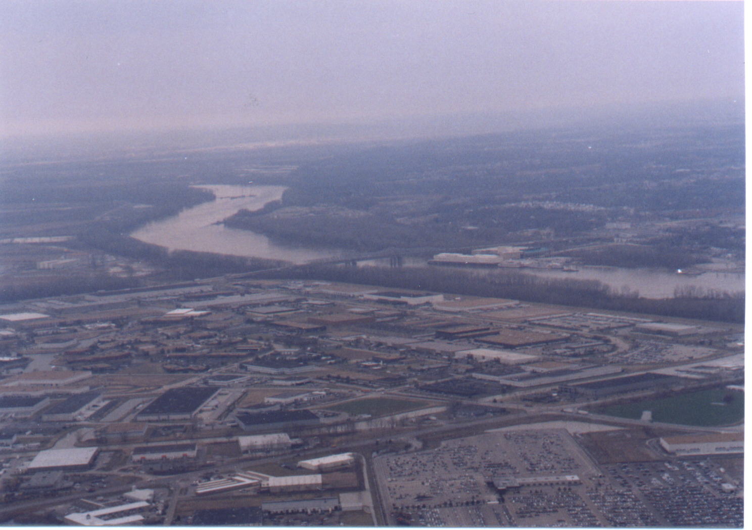 Figure 1. View of the Missouri River at St. Charles Station Casino
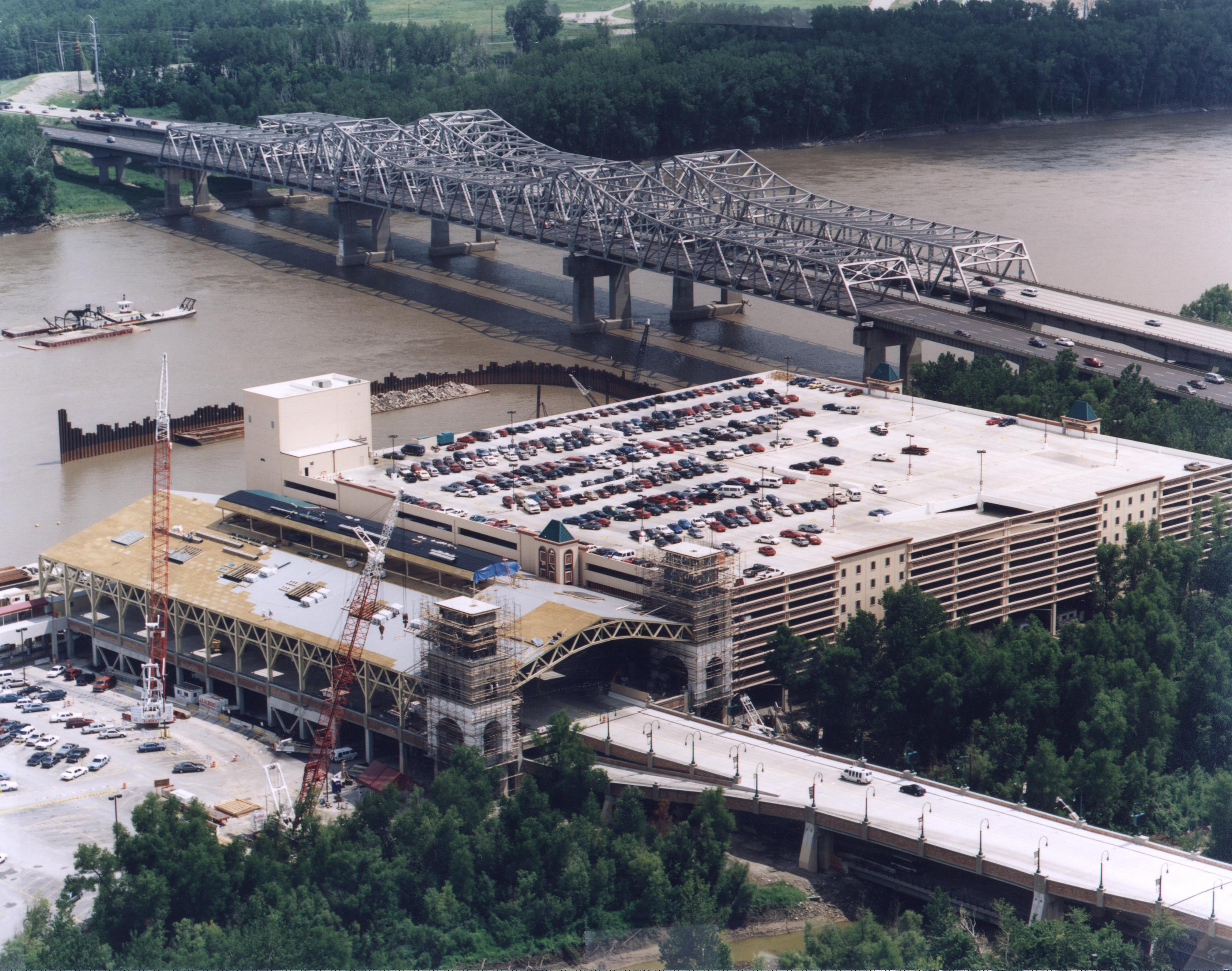 Sedimentation Study on the Missouri River at St. Charles Station Casino
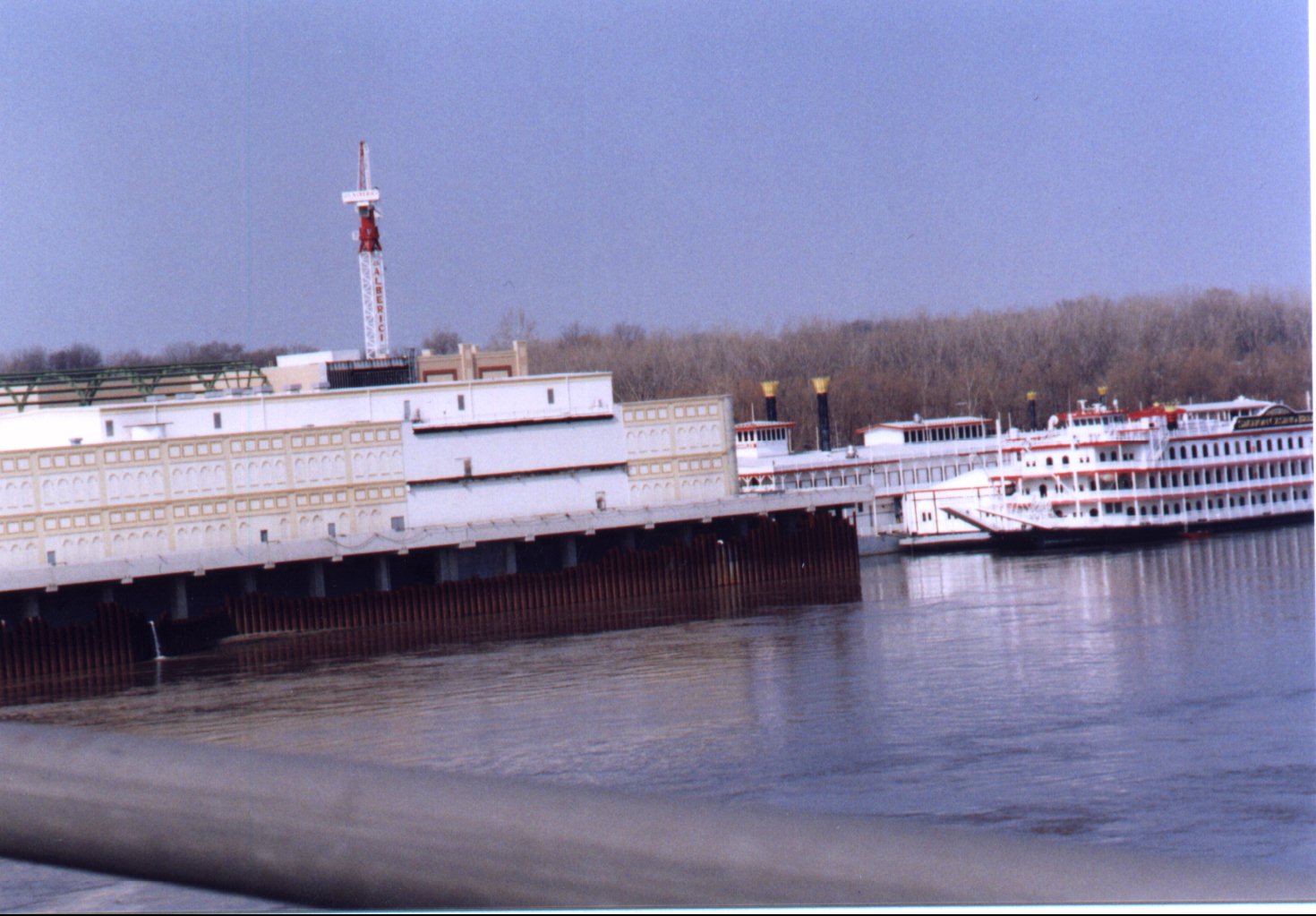 Figure 3. SCSC cofferdam and the gambling casino
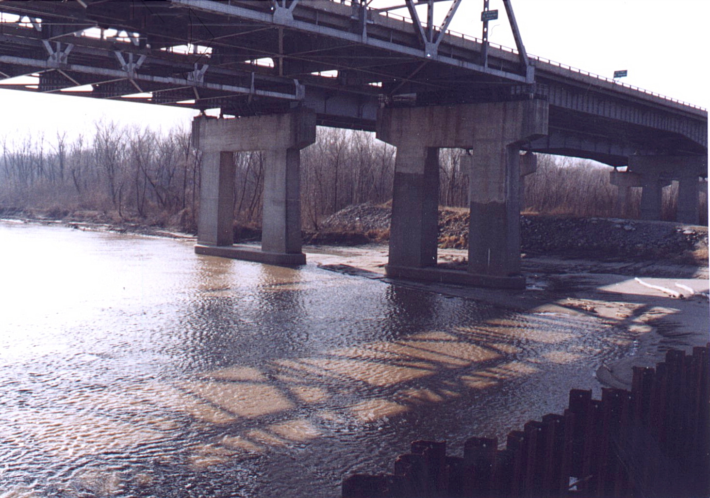 Figure 4. Sediment deposition upstream from the cofferdam
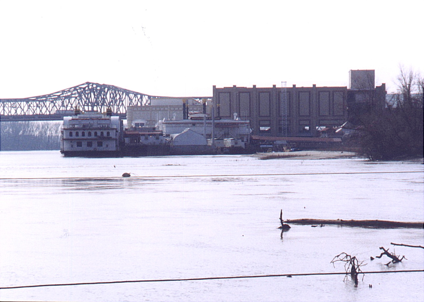 Figure 5. SCSC flotilla region view from downstream
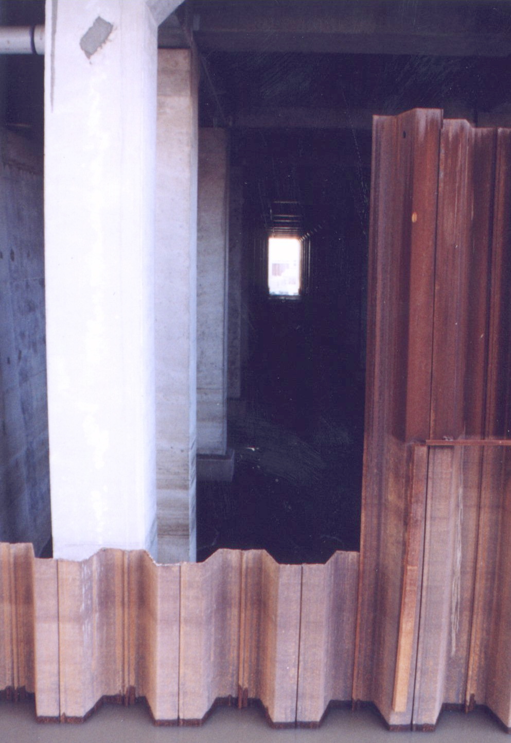 Figure 6. A passageway through the cofferdam that was considered for mobilizing fine sediments in the wake region
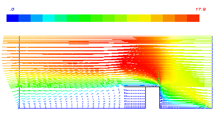 Figure 7. Computed flow patterns around the cofferdam
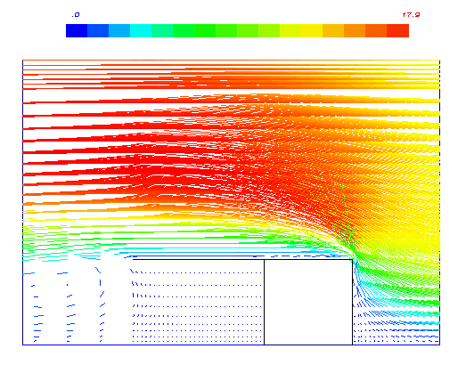 Figure 8. Flow field near cofferdam with proposed diversion wall